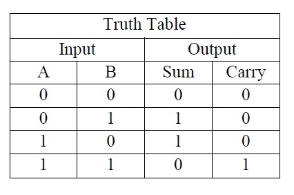
The Half Adder is a so called combinational circuit, to add two single binary digits and provide the output plus a carry value. It has two inputs, called A and B, and two outputs S (Sum) and C (Carry).
The relation between inputs (A, B) and the outputs (Sum. Carry) is described by the so called Truth Table. The Truth Table for the Half Adder is as follows:
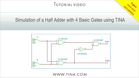
In this tutorial video we created and tested a Half Adder circuit using TINACloud.
We used basic OR, AND, NOT (Inverter) gates, High-Low switches and Voltage pins for the outputs.
Click here to watch our tutorial video and learn more.
You can learn more about TINA here: www.tina.com
You can learn more about TINACloud here: www.tinacloud.com