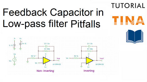
Creating and simulating an RLC circuit using TINACloud

Creating and simulating an RLC circuit using TINACloud

Click here to watch our new tutorial video where we created analyzed an RLC circuit.

First we created the circuit then performed Transient and AC numerical analysis. We also created the same results with Symbolic Analyses by creating and evaluating the accurate analytic expressions provided by Symbolic Analysis.

We added the diagrams and the formulas to the Schematic Editor screen and TINACloud automatically saved all of these in the same RLC circuit.TSC file.

Click here to watch our tutorial video and learn more.

You can learn more about TINA here: www.tina.com

You can learn more about TINACloud here: www.tinacloud.com

Arduino blinking LED simulation using TINACloud and video of the real working hardware (in Hebrew language)

Arduino blinking LED simulation using TINACloud and video of the real working hardware (in Hebrew language)

Click here to watch our Hebrew language tutorial video and learn more.

In this tutorial video we created, simulated and built an Arduino controlled blinking LED circuit using TINACloud and the real life Arduino UNO board.

First, we created the circuit using the schematic editor of TINACloud. 

Next we loaded, explained and compiled the Arduino code.

Then we ran Transient Analysis to show the waveform.

We use the live interactive mode to show the blinking.

Finally we added a video of the real life working circuit.

Click here to watch our Hebrew language tutorial video and learn more.

You can learn more about TINA here: www.tina.com

You can learn more about TINACloud here: www.tinacloud.com

Arduino blinking LED simulation using TINACloud and video of the real working hardware

Arduino blinking LED simulation using TINACloud and video of the real working hardware

Click here to watch our tutorial video and learn more.

In this tutorial video we created, simulated and built an Arduino controlled blinking LED circuit using TINACloud and the real life Arduino UNO board.

First, we created the circuit using the schematic editor of TINACloud. 

Next we loaded, explained and compiled the Arduino code.

Then we ran Transient Analysis to show the waveform.

We use the live interactive mode to show the blinking.

Finally we added a video of the real life working circuit.

Click here to watch our tutorial video and learn more.

You can learn more about TINA here: www.tina.com

You can learn more about TINACloud here: www.tinacloud.com

How to create and simulate an Arduino controlled blinking LED circuit with TINACloud?

How to create and simulate an Arduino controlled blinking LED circuit with TINACloud?

Click here to watch our tutorial video and learn more.

In this tutorial video we will create and simulate the Arduino controlled blinking LED circuit on the screen with TINACloud.

First, we created the circuit using the schematic editor of TINACloud. Next we loaded and compiled the Arduino code.

Let’s quickly follow the operation of the C code:

Initialize the digital pin LED_BUILTIN as an output.

Call the loop function to create an infinite loop for the instructions between the opening { and closing } braces

Turn the LED On with a logic HIGH voltage.

Create a 5ms delay

Turn the LED Off with a logic Low voltage.

Create a 5ms delay

Return to the { opening brace  of the loop function.

Now Compile the code by clicking the “Compile” button.

Next click the “Save all”button to save the compiled code.

Click here to watch our tutorial video and learn more.

You can learn more about TINA here: www.tina.com

You can learn more about TINACloud here: www.tinacloud.com

Tutorial Video for Simulation of a Half Adder Circuit with 4 Basic Gates using TINACloud

Tutorial Video for Simulation of a Half Adder Circuit with 4 Basic Gates using TINACloud

The Half Adder is a so called combinational circuit, to add two single binary digits and provide the output plus a carry value. It has two inputs, called A and B, and two outputs S (Sum) and C (Carry).

The relation between inputs (A, B) and the outputs (Sum. Carry) is described by the so called Truth Table. The Truth Table for the Half Adder is as follows:

In this tutorial video we created and tested a Half Adder circuit using TINACloud.

We used basic OR, AND, NOT (Inverter) gates, High-Low switches and Voltage pins for the outputs.

Click here to watch our tutorial video and learn more.

You can learn more about TINA here: www.tina.com

You can learn more about TINACloud here: www.tinacloud.com