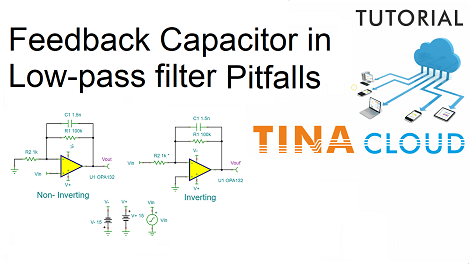
Adding a capacitor in parallel with the feedback resistor of an op amp is an easy way of accomplishing low-pass filtering.
This technique works quite well in an inverting amplifier but not necessarily in a non-inverting amplifier.
If the non-inverting amplifier has high gain, the filtering is not bad, but inferior to the inverting case.
We will illustrate the above by creating and analyzing both circuits. We will use the Spice model of the OPA132 Operational Amplifier.
1. Creating the non-inverting circuit
First we will create the non-inverting circuit. As the components are inserted using their default values, next we will show how to enter the required component values.
2. Creating the inverting circuit
As the two circuits are similar,we will edit and copy the Non-Inverting circuit and then modify where needed.
3. Testing the circuits
In order to step R2, set Parallel Stepping in the Mode Dialog under the Analysis menu. This will step both R2 resistors parallelly.
Select Mode from the Analysis Menu, then in the Analysis Mode dialog select Parameter Stepping from the list.
Next, select Parallel stepping from the Stepping Mode list.
We will test first the Non-Inverting circuit.
Click the output voltage pin of the Non-Inverting circuit and Set the Display signal to „Yes” mode, or check if it is already set so.
Next click at the output voltage pin of the Inverting circuit and set the Display signal to No.
From the Analysis menu select AC Analysis, then AC Transfer Characteristic.
For the lowest curve with a gain of 6db the stopband attenuation is 6dB only.
Now test the Inverting circuit.
To learn more watch our tutorial video.
You can learn more about TINA here: www.tina.com
You can learn more about TINACloud here: www.tinacloud.com