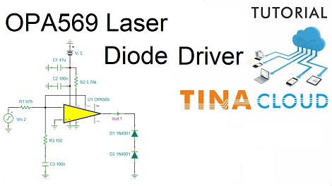
In this tutorial we will demonstrate how to create a Laser Driver circuit with a negative voltage supply using the Spice model of the OPA569 operation amplifier.
First, we will create the circuit like the one on this sample schematic:
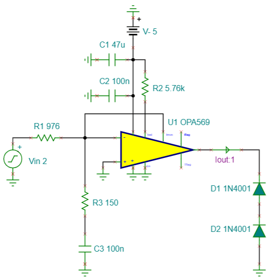
As it can be seen, we will use 3 Resistors, 3 Capacitors, 2 Diodes, a Voltage Generator, a Battery, a Current Arrow and of course some Grounds.
Some of the components need to be rotated. We will show how to rotate components before or after they are placed on the schematic editor window.
Next, we will present how to set the default component values.
After the circuit is complete we will test the circuit by running Transient, AC analysis and finally DC analysis.
We will also add one of the diagrams and a title to the circuit.
To learn more watch our tutorial video.
You can learn more about TINA here: www.tina.com
You can learn more about TINACloud here: www.tinacloud.com