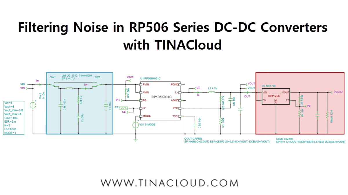
We’ve released a new video tutorial demonstrating how to analyze, design and implement appropriate input and output filtering for an RP506 Series Step-Down DC-DC Converter using TINACloud, and verify the results to ensure stable, low-noise operation.
DC-DC converters are indispensable in modern electronic systems for efficiently stepping voltages up or down. However, their inherent switching operation introduces conducted noise and ripple on both the input and output rails.
Although usually small in amplitude, these disturbances can become critical in sensitive applications such as precision measurement, RF front-ends, or high-speed digital circuits.
We will use the RP506K001C_#Steady.tsc file from the TINA Examples\ Nisshinbo folder.
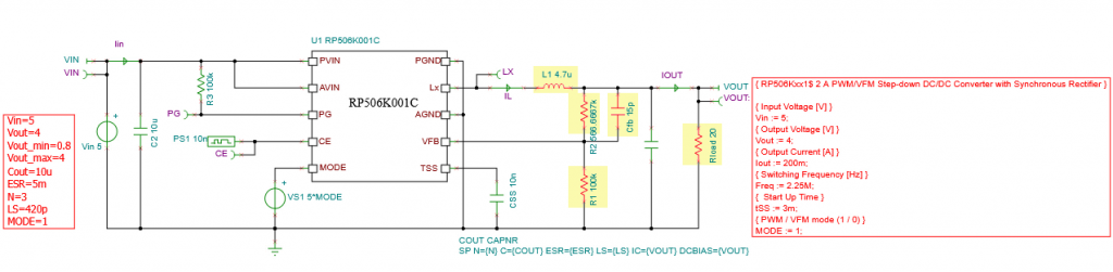
First we will redesign the circuit using the Design Tool in TINACloud to obtain Vout = 4 V. The results of the quick analytic calculation appear instantly:
After closing this window, the resulting circuit with the changed components is displayed.
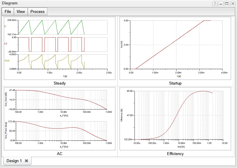
Next, calculate the ripple in the input current (Iin) and output voltage (Vout). Run Transient Analysis. The steady state waveforms appear:
Select Ripple… from the Process menu of the Diagram window to calculate the absolute and relative ripple of Vout and Iin.
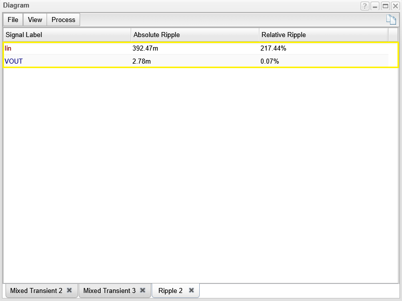
As we can see, the ripple of the output voltage is quite small – only 2.78 mV, while the ripple in the input current is very high but may be acceptable due to the filtering in the main power supply. However, as mentioned in the introduction, these disturbances may cause problems in some applications and therefore must be filtered out.
To further filter the output voltage, a common solution is to add an LDO regulator, as it also acts as a low-pass filter that attenuates high-frequency components.
The result is a cleaner, more stable output voltage – which is especially important for sensitive analog or RF circuits, microcontrollers, or precision sensors.
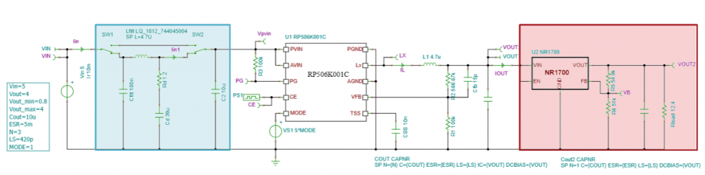
Let’s add an NR1700 Adjustable Output LDO Regulator to the output (available in TINA), and an RLC filter to the input.
We get the following circuit:
Now, calculate the transient waveforms and the ripple of this circuit. Using transient analysis, we obtain the following waveforms:
Finally, let’s calculate the ripple values.
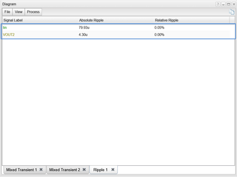
The ripple values are now very low – within the microvolt and microampere range – making them acceptable even in sensitive applications.
This concludes our presentation on filtering the input and output noise of DC-DC converters.
You can learn more about TINACloud here: www.tinacloud.com
You can learn more about TINA here: www.tina.com
Explore more content from our channel: https://www.youtube.com/@TinaDesignSuite