Shields, Breakout Boards and Modules in TINACloud
Nowadays, there are many opportunities to extend the capabilities of a microcontroller board, for example, shields, breakout boards and modules. All of these are open-source hardware, which means that the boards have detailed descriptions, schematics, PCB files, hookup guides and examples.
In this video, we will explain what these hardware devices are and how to use them with an Arduino Uno in TINACloud.
Arduino Shields
Arduino shields are boards that can be plugged on top of Arduino boards. They have the same pinout as the main board, and these pin names are represented on the PCB. The different shields have different capabilities (DC motor control shield, relay shield, LCD shield, etc.). Using them is time and cost effective.
Breakout Boards
The basic concept of breakout boards is to use just a single electrical component on each board. The pins of the component are wired out, and their names are represented on the board. This concept allows for easy usage and reusability. Breakout boards are usually smaller than shields. Usually, a breakout board represents a small functional circuit. These can be sensors, drivers, displays, etc. Breakout boards can be used with any microcontroller.
Modules
Some manufacturers produce breakouts that use the same x-pin header or connector on every board. These breakout boards are called modules.
You can place shields, breakout boards and modules in TINACloud from TINACloud’s Logic ICs-MCUs toolbar.
Let’s see how some of these examples work.
4 Relays Shield
The 4 Relays Shield provides a solution to control high power loads that cannot be controlled by the Arduino itself because of the limitations of the digital IO-s. The 4 Relays Shield has four relays, which are 2-pole changeover contacts in order to increase the current limit of the output. The main advantage of the Arduino system is that with the following simple program, which is included in the example, we can operate the relays and light up the LEDs sequentially.
Click the TR button to start the simulation. As expected, the LEDs light up one by one and then turn off one by one. Now let’s see how this looks with the real hardware.
LCD keypad shield
Open the next example, “LCD keypad shield-Arduino Uno.tsc,” from the same folder.
The Arduino LCD shield is fit for the Arduino Uno board. It contains a 16×2 LCD display and six momentary push buttons. Pins 4, 5, 6, 7, 8, 9 and 10 are used to interface with the LCD. Analog pin 0 is used to read the five push buttons.
The next example is a module example. You can find it in the Grove Modules folder in TINACloud.
Grove LED module
The Grove – LED module contains an LED light source. In addition, it has a potentiometer on-board to manage the power requirements of the LED.
Our last example is a breakout board example. Open it from the SparkFun Breakouts folder.
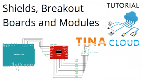
SparkFun 74HC595 Breakout board
The SparkFun 74HC595 breakout board contains the SOIC version of the 74HC595 shift register IC. The pins of the IC are wired out and marked on the board. The serial in and out pins are located on the opposite side of the board to allow easy chainable functionality.
The code will write the word HELLO sequentially on the 8-segment display.
In this video tutorial, we demonstrated two basic shields, a module and a breakout board for Arduino. Stay tuned to our YouTube channel to learn more about Arduino and its accessories.
To learn more please click here.
You can learn more about TINA here: www.tina.com
You can learn more about TINACloud here: www.tinacloud.com