
Good news! As a 2020 holiday gift we have added Current flow and voltage animation to TINACloud.
And yes, the same feature will be also available next year in the offline versions of TINA.
Current and voltage animation is an especially useful pedagogical tool. You can make outstanding presentations showing animated current flows and voltages for your presentations, textbooks, or assignments.
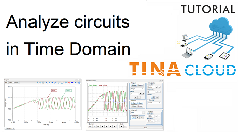
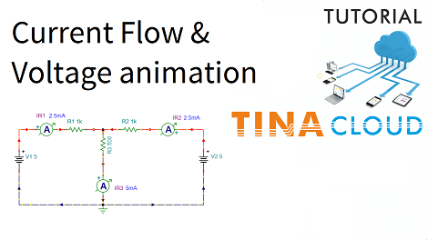
In this tutorial video, we demonstrate the DC current flow and voltage animation feature of TINACloud.
We present this through a DC example included in TINACloud.
To see the animation feature, first we have to enable it in the Options dialog under the Analysis menu.
Next, we click the DC button.
The program will demonstrate the current flow with running dashes. The program will also mark the direction of the currents with filled current arrows.
The color of the dashes also indicates the value of voltages. Positive values are red, and negative values are blue. When the voltage reaches zero the color turns black.
You can read more about this topic including animation in time here.
To watch our tutorial please click here.
You can learn more about TINA here: www.tina.com
You can learn more about TINACloud here: www.tinacloud.com

Happy Holidays!