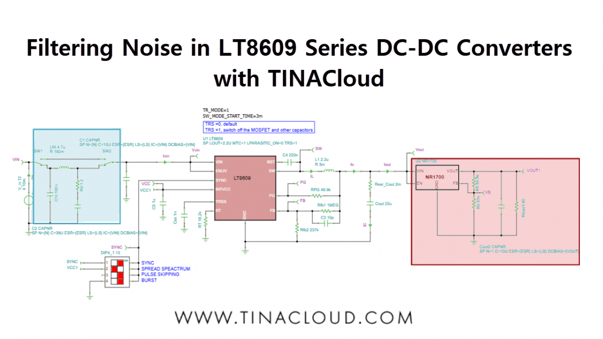
In this tutorial, we will demonstrate how to analyze, design, and implement appropriate input and output filtering for an LT8609 Series Step-Down DC-DC Converter using TINACloud, and verify the results to ensure stable, low-noise operation.
DC-DC converters are indispensable in modern electronic systems for efficiently stepping voltages up or down. However, their inherent switching operation introduces conducted noise and ripple on both the input and output rails.
Although usually small in amplitude, these disturbances can become critical in sensitive applications such as precision measurement, RF front-ends, or high-speed digital circuits.
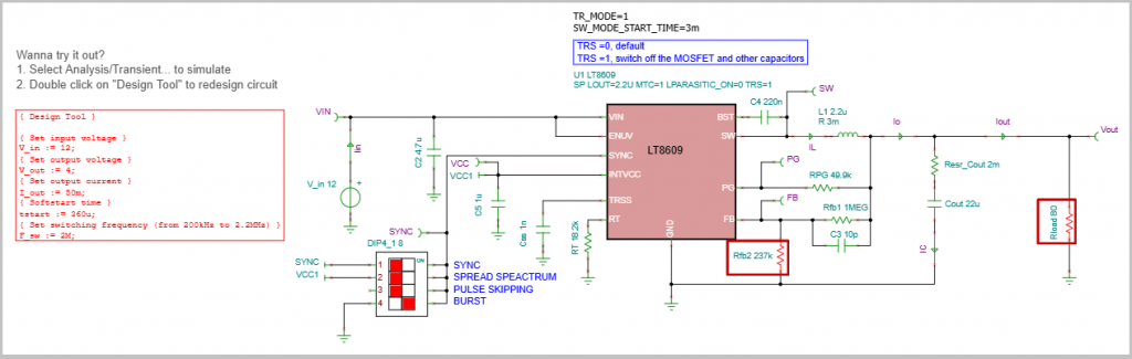
1. Initial Circuit Setup and Redesign
To begin the analysis, we use the simulation environment.
Start by opening the LT8609 Steady State Analysis.tsc file found in the TINA Examples/Analog Devices folder. The first objective is to redesign the circuit to meet a specific output voltage requirement.
Using the Design Tool in TINACloud (accessible via Tools menu/ “Re-design this Circuit…”), we set the required output voltage (Vout) to 4 V. Once the value is entered, pressing Run executes the quick analytic calculation, and the necessary component changes are instantly applied to the displayed circuit.
2. Analyzing Initial Noise and Ripple
Calculating Initial Ripple
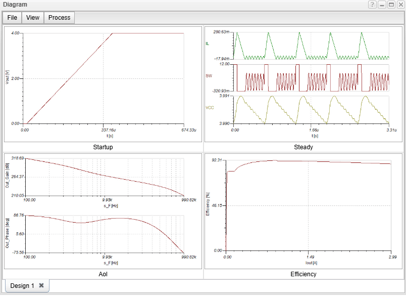
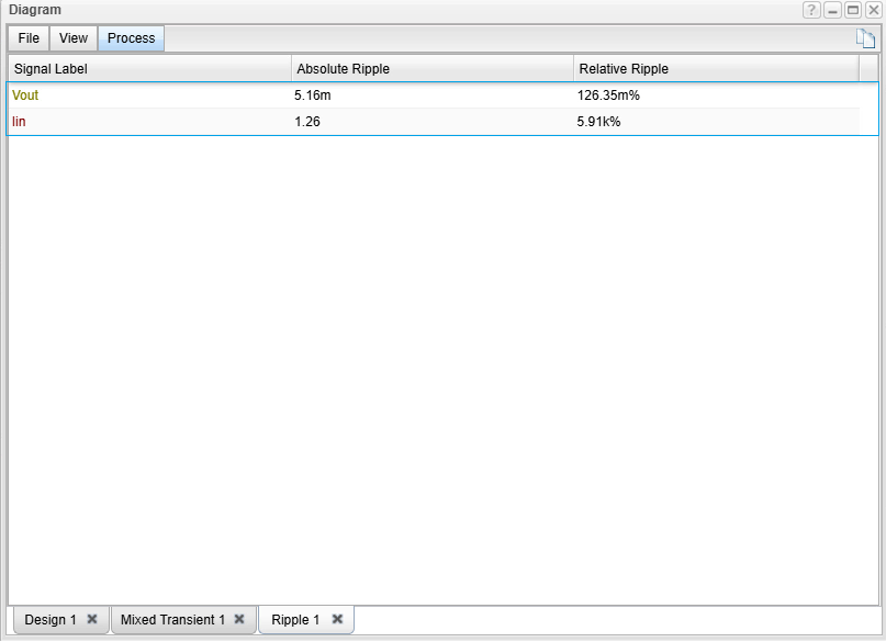
We calculate the ripple in the input current (Iin) and the output voltage (Vout). By running a Transient Analysis in TINACloud, the steady-state operating waveforms appear. To get the numerical values, select Ripple… from the Process menu of the Diagram window. This calculates and displays the absolute and relative ripple values.
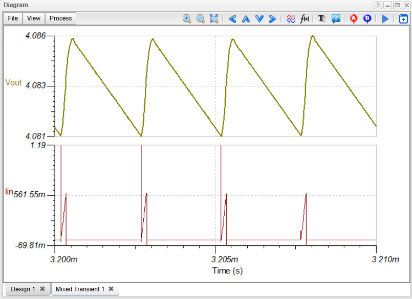
The Problem: High Input Ripple
The result is displayed in new window. As we can see, the ripple of the output voltage is quite small – only 5.16 mV, while the ripple in the input current is very high but may be acceptable due to the filtering in the main power supply.
However, as mentioned in the introduction, these disturbances may cause problems in some applications and therefore must be filtered out.
The result is a cleaner, more stable output voltage – which is especially important for sensitive analog or RF circuits, microcontrollers, or precision sensors.
3. Implementing Low-Noise Filtering
To achieve a cleaner, more stable output voltage—critical for sensitive analog, RF, or precision sensor circuits—we modify the design by adding external filtering components.
Using the circuit editor in TINACloud, we introduce two key filtering stages:
- Output Filtering: An NR1700 Adjustable Output LDO Regulator (Low Dropout Regulator) is added to the output. LDOs are highly effective at suppressing ripple and providing a stable voltage even when the input (from the DC-DC converter) has residual noise.
- Input Filtering: An RLC filter is added to the input rail to significantly attenuate the large input current ripple.
Filtering Noise in LT8609 Series DC-DC Converters with TINACloud: Adding an
LDO Regulator and an RLC filter
4. Verification of Filter Effectiveness
With the filters in place, we repeat the analysis to confirm the noise reduction.
We perform a new Transient Analysis to obtain the updated waveforms and then use the Ripple… function again to check the final noise levels.
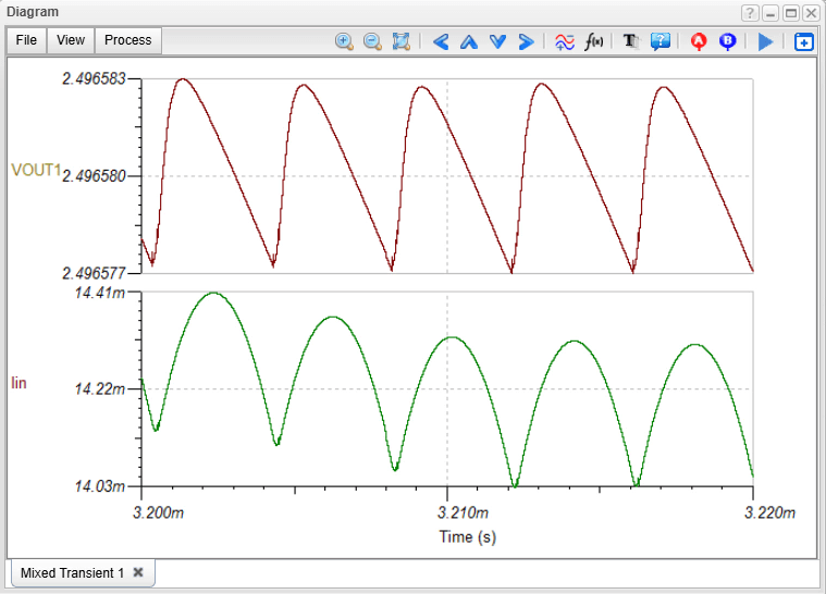
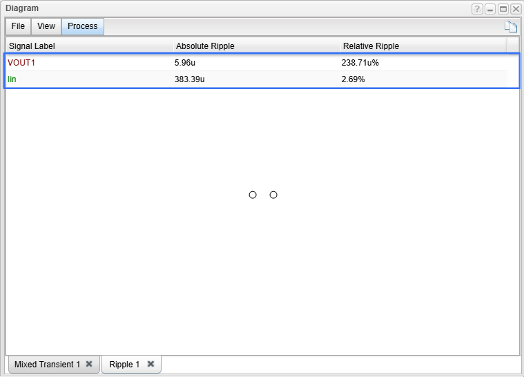
The Final Result
The ripple values are now drastically reduced, falling into the microvolt and microampere range. This demonstrates the success of the filtering strategy, resulting in a cleaner output that is acceptable even for the most demanding, sensitive applications.
This concludes the demonstration of how to effectively filter the input and output noise of DC-DC converters using TINACloud simulation.