10Hz Active Low-Pass Filter

10Hz Active Low-Pass Filter

This “10Hz Active Low-Pass Filter” circuit offers a very low frequency cutoff and it has the ability to operate on single supply voltages. As shown, this is a second- order unity- gain Butterworth low- pass filter using a Sallen- Key topology. One advantage of a Sallen- Key LPF over one configured as a Multiple Feedback LPF is that it is non-inverting–therefore an input signal with a positive DC offset can be accomodated. A low input bias current op amp is required for a very low frequency low- pass filter as the R values are necessarily high. Thermal noise contributed by these resistors, however, can be reduced by reducing their values by an order of magnitude together with increasing the capacitor values by an order of magnitude. Resistor thermal noise will thereby be decreased by the square- root of 10.  (Circuit is created by Neil P. Albaugh,  TI – Tucson )

10Hz Active Low-Pass Filter circuit:

Active low-pass filter-blog


Online Simulation of the “10Hz Active Low-Pass Filter” Circuit

The great feature of the TINA circuit simulator that you can analyze this circuit immediately with TINACloud the online version of TINA. Of course you can also run this circuit in the off-line version of TINA.

Click here to invoke TINACloud and analyze the circuit, or watch our tutorial video!

You can send this link to any TINACloud customers and they can immediatelly load it by a single click and then run using TINACloud.

Michael Koltai
www.tina.com

High-Capacitance Line Driver

High-Capacitance Line Driver

Capacitive loads invite amplifier instability by reducing phase margin. Instability can be prevented by isolating  the load capacitance from the amplifier output by a small resistor R3. To eliminate a voltage drop error when current is drawn through that resistor, DC feedback is sensed on the load side of R3. High- frequency feedback is provided by C2. The load capacitance was stepped from 100pF to 1uF and the results are shown below; no gain peaking is evident. Bypass capacitors are not shown. (Circuit is created by Neil P. Albaugh  TI-Tucson)

High-Capacitance Line Driver circuit:

High-capacitance line driver-blog


Online Simulation of the “High-Capacitance Line Driver” Circuit

The great feature of the TINA circuit simulator that you can analyze this circuit immediately with TINACloud the online version of TINA. Of course you can also run this circuit in the off-line version of TINA.

Click here to invoke TINACloud and analyze the circuit, or watch our tutorial video!

You can send this link to any TINACloud customers and they can immediatelly load it by a single click and then run using TINACloud.

Michael Koltai
www.tina.com

Simple Absolute Value Amplifier

Simple Absolute Value Amplifier

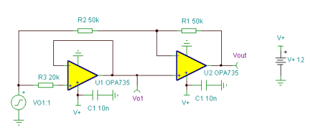
The rail- to- rail output characteristics of these CMOS op amps allow them to swing very close to their negative supply rails–ground. By using a non-inverting amplifier U1 to swing only positive (due to its not being capable of swinging below ground), this op amp acts like a perfect rectifier. For positive inputs, the input to the inverting amplifier U2 sees a voltage that is equal to the voltage on its non-inverting input (from follower U1), therefore the net gain of U2 is +1V/V. For negative inputs, the + input to the inverting amplifier U2 sees a voltage that is as close as U1 can swing to its negative supply rail (ground); therefore the net gain of U2 is -1V/V. This output of U1 is amplified by the noise gain of U2 and appears as an offset error on the output of the absolute value amplifier.

This is the primary limitation to accuracy with very small input signals.

This absolute- value amplifier has a gain of +1V/V and has an input range of +/- a few mV to -10V to +10V. (Circuit is created by Thomas Kugelstadt & Neil P. Albaugh, TI – Tucson)

Simple Absolute Value Amplifier circuit:
Simple absolute value amplifier
Simple Absolute Value Amplifier Circuit
Online Simulation of the “Simple Absolute Value Amplifier” Circuit

The great feature of the TINA circuit simulator that you can analyze this circuit immediately with TINACloud the online version of TINA. Of course you can also run this circuit in the off-line version of TINA.

Click here to invoke TINACloud and analyze the circuit, or watch our tutorial video! 

You can send this link to any TINACloud customers and they can immediatelly load it by a single click and then run using TINACloud.

Michael Koltai
www.tina.com

Low-Pass Filter With Very Low DC Offset

Low-Pass Filter With Very Low DC Offset

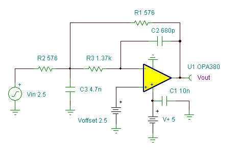
This filter’s unusually low DC offset is due to the use of an OPA380 at U1. While this amplifier is usually employed as a transimpedance amplifier, it can also be used as an inverting op amp. In this configuration it provides wide bandwidth with extremely low input offset voltage and drift.

The OPA380 is a monolithic 85MHz GBW CMOS op amp with an internal auto- zeroed integrator. This integrator forces the high-speed op amp input offset and drift to virtually zero.

This 100kHz “Low-Pass Filter With Very Low DC Offset” circuit is a two- pole multiple- feedback filter with a Butterworth response. This filter has a DC gain of 1V/V or 0dB. Above the  -3dB corner frequency its response is close to theoretical up to 10MHz; above this frequency the finite GBW of U1 prevents much additional filter rolloff. An OPA380 is not suitable for a Sallen- Key active filter; that topology requires an op amp to be used as a non-inverting amplifier. The OPA380’s non-inverting input is a very low bandwidth integrator input. (Circuit is created by Neil P. Albaugh, TI – Tucson )

“Low-Pass Filter With Very Low DC Offset” Circuit:
LPF with very low DC offset-blog
“Low-Pass Filter With Very Low DC Offset” Circuit
Online Simulation of the “Low- Pass Filter With Very Low DC Offset” Circuit

The great feature of the TINA circuit simulator that you can analyze this circuit immediately with TINACloud the online version of TINA. Of course you can also run this circuit in the off-line version of TINA.

Click here to invoke TINACloud and analyze the circuit, or watch our tutorial video!

You can send this link to any TINACloud customers and they can immediatelly load it by a single click and then run using TINACloud.

Michael Koltai
www.tina.com
Capacitance Bridge

Capacitance Bridge

This circuit below is a capacitance bridge; it detects the matching between a reference capacitance C1 and an unknown capacitance, Cx. It uses an instrumentation amplifier in an unusual topology– a sine wave drives the two input op amps’ non- inverting inputs (ordinarily the IA inputs) and the internal 25k feedback resistor of each op amp forces that sine wave to appear at the op amp’s inverting inputs (ordinarily the IA gain resistor connections). The impressed AC voltage across each capacitor causes current to flow in each feedback resistor and this creates a voltage at the output of each of the two input op amps. The third IA stage, a differential amplifier, subtracts the two voltages. Thus, when Cx = C1, the output voltage is zero.

A higher or lower capacitance at Cx unbalances the bridge

and an output results that is proportional to the capacitance difference; a high/low mismatch is indicated by a 180 degree phase difference.

A synchronous detector (aka phase- sensitive demodulator) driven by F and low- pass filtered will result in a capacitance bridge DC output that is at null when Cx = C1.  The sensitivity of the bridge is proportional to F, both in amplitude and frequency, and to the reference capacitance C1. Higher frequencies result in higher output voltages but the inevitable IA CMRR roll- off at high frequencies will reduce the depth of the null voltage.  An advantage of this circuit is that it is quite simple and it allows both capacitors to be ground- referenced.  (Circuit is created by Neil P. Albaugh,  TI-Tucson)

Capacitance Bridge circuit:

Capacitance Bridge-blog

Online Simulation of the “Capacitance Bridge” Circuit

The great feature of the TINA circuit simulator that you can analyze this circuit immediately with TINACloud the online version of TINA. Of course you can also run this circuit in the off-line version of TINA.

Click here to invoke TINACloud and analyze the circuit, or watch our tutorial video!

You can send this link to any TINACloud customers and they can immediatelly load it by a single click and then run using TINACloud.

Michael Koltai
www.tina.com