
In this post, we’ll walk through how to convert digital circuit files originally created in offline Multisim formats such as MS13 and MS14, and run them directly inside TINACloud. The same conversion process is available in the offline version of TINA, where you can perform it locally as well.
We’ll cover three examples, each illustrating a different type of circuit: a purely digital up/down counter, a mixed-mode digital dice, and an 8-bit PIC microcontroller running both assembly and C code.
Click here or on the image above to watch this blog presented as a video tutorial.
Example 1: 8-bit Counter
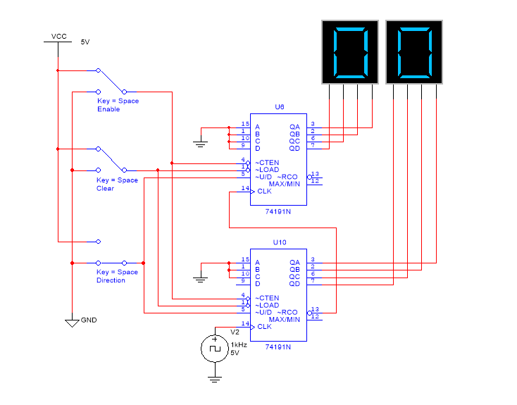
Our first example is an 8-bit counter — specifically, a two-digit synchronous up/down counter built from two 74191N counter ICs and two 7-segment HEX displays. Interactive switches let you:
- Enable or disable the counting process.
- Clear the counters completely.
- Control the direction of the count (upward or downward).
With the Counter.ms14 file already saved locally, we use the Upload command to bring it into TINACloud, where it’s converted automatically.
To run the simulation, press the TR button and enable counting with the Upwards switch. The counter starts from zero and climbs steadily. Once the U2 display reaches F, U1 advances to 1 and U2 rolls back to 0. Disabling counting with the Upwards switch, clearing the counters, flipping the direction, and re-enabling counting causes the counter to count downward starting from FF.
Replacing the switches for a fully digital version
If you replace the standard switches with TINACloud’s Digital High-Low switches, the circuit becomes fully digital, letting you observe the digital states of every node. Press the Dig button to enter this view.
Example 2: A Mixed-Mode Digital Dice
Our second example is a mixed-mode circuit — a digital dice. The design pairs an NE555 analog oscillator, which provides the clock pulses, with a CD4017 digital decade counter.
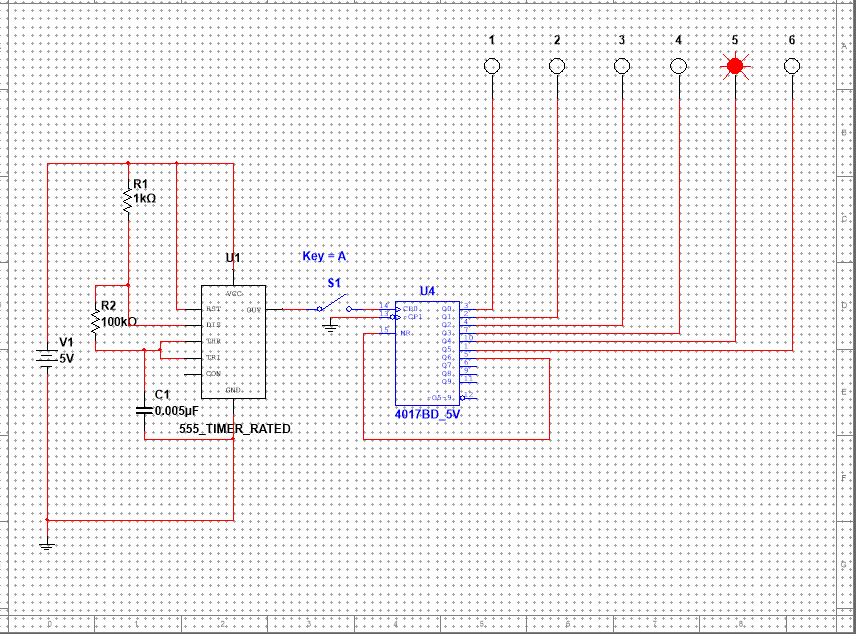
With the MS14 circuit file already on hand, we upload it into TINACloud using the standard procedure. The CD4017 is designed to convert incoming clock pulses into a sequential HIGH signal across its ten decoded outputs, Q0 through Q9. In this circuit, however, output Q6 is wired back to the Master Reset (MR) pin: the moment the counter reaches 6, it resets to zero instantly. The result is a circuit that effectively cycles through positions 1 to 6.
To see it in action, start the simulation by pressing the TR button, then click S1 to close the switch. The TINACloud logic indicators now light up one by one, moving from left to right. Clicking the switch again opens it, interrupting the clock pulses; the counting stops immediately, leaving one indicator HIGH at a random position between 1 and 6. This is why this circuit can be considered a digital dice. Opening and closing the switch repeatedly causes the sequence to “freeze” at a different indicator almost every time, neatly demonstrating the interaction between the continuous analog oscillator and the digital counter.
Example 3: 8-bit PIC Microcontroller
Our final example features an 8-bit PIC microcontroller (MCU). While microcontrollers are supported only in the offline version of Multisim, they are fully operational in both the offline and cloud versions of TINA.
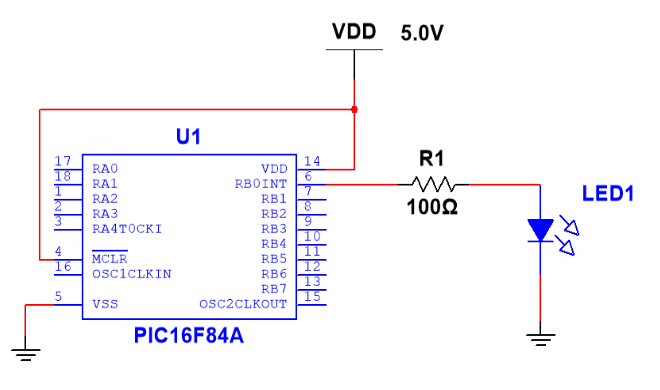
8-bit PIC Microcontroller in Multisim
The circuit, an “LED Blinker,” periodically toggles an LED on and off. Moving it from Multisim to TINACloud requires both the circuit file and the microcontroller program file. When you save the PICLedBlink.ms14 file in Multisim, the .ASM assembly file isn’t exported automatically — you have to extract it manually:
- Double-click the MCU symbol in Multisim.
- Open the Code tab and click Properties to launch the MCU Code Manager.
- Click the icon on the right side of the “Show machine code file…” line.
- In the file list, right-click PicLedBlink.asm and open it in Notepad.
- Save it as PICLedBlink.asm in the same folder as your .ms14 file.
- Compress both files into a single archive named PICLedBlink.zip.
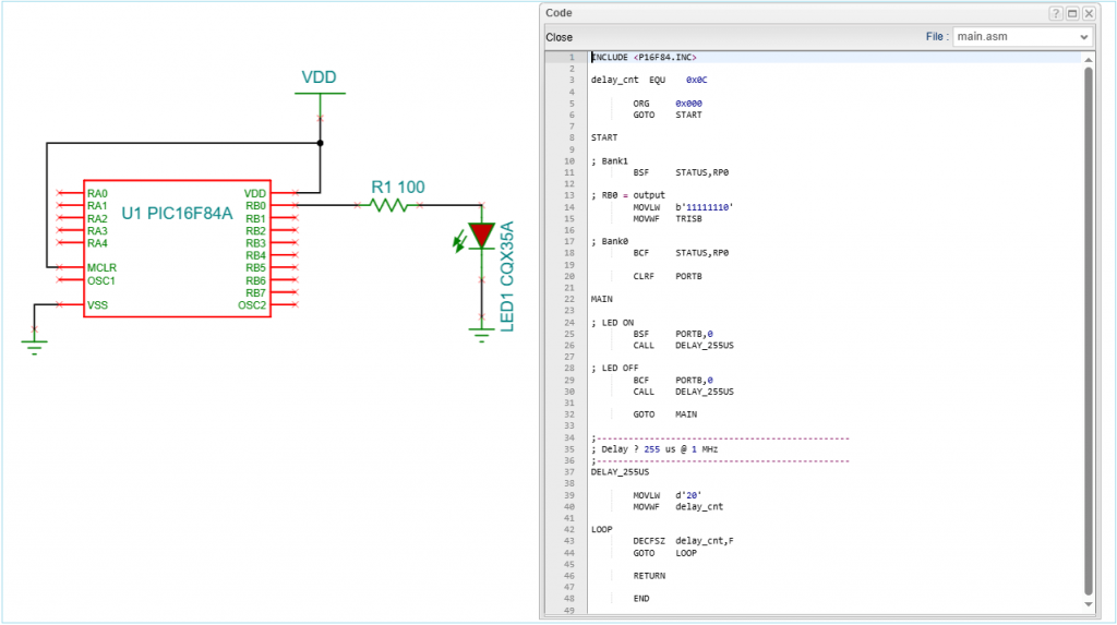
Upload the ZIP file to TINACloud as usual, and the schematic diagram of the same circuit appears. In the MCU symbol in TINA and TINACloud, the MCU program file is directly available.
To view the MCU program file — in this example, the .asm file — double-click the MCU symbol, click the “…” icon on the right side of the MCU Code line, and choose Preview. The assembly language code appears. You can also upload your own assembly code by selecting Upload. Pressing the TR button starts the simulation, and the LED begins to blink immediately.
Debugging code execution with the MCU Debugger
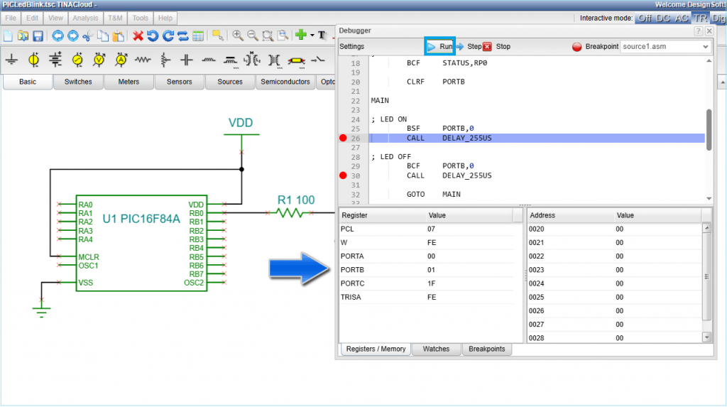
TINACloud also lets you study code execution using the built-in MCU Debugger. Enable MCU Code Debugger in the Analysis menu, then press the TR button again to launch the debugger window. From here, you can:
- Use the Step button to execute code line-by-line while monitoring Registers and Memory.
- Set Breakpoints by clicking on a line of code or using the Breakpoint button.
- Press Run, and the program will halt at your designated points.
Pay close attention to Port B, which directly controls the LED.
C-Code and Arduino
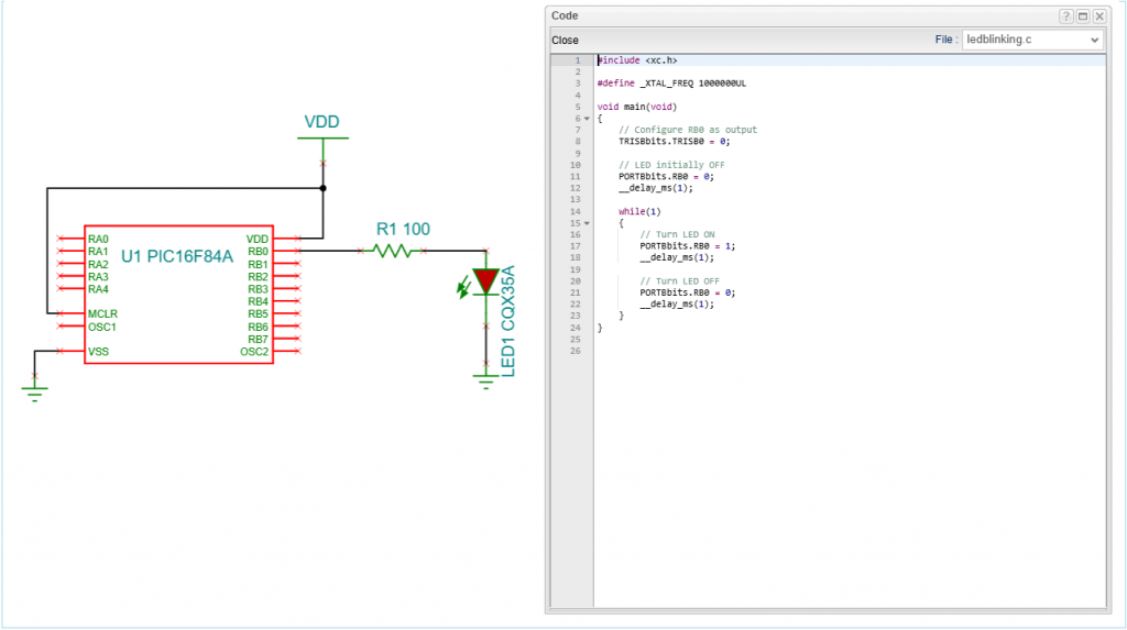
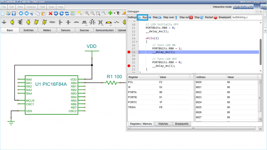
While assembly is the most powerful tool, you can also program MCUs in TINACloud using C, which is much easier to write and read. Open PICLedBlink_C_Code.tsc — the circuit looks identical to the previous one, but the PIC is now running on C-code. Press the TR button to start the simulation, then double-click the MCU and click the “…” at the end of the MCU-code line, selecting Preview to view the source. As you can see, C-code is generally much easier to read and follow, and you can debug it in much the same way as assembly.
These days, the Arduino platform is more often used in place of programming MCUs directly in assembly or even in C, thanks to its ease of use. The Arduino platform is also supported in both TINACloud and TINA. For more information, see our Arduino tutorials on our YouTube channel, for example “Arduino blinking LED simulation using TINACloud.”
Learn More
For more information, visit www.tina.com or our YouTube channel at www.youtube.com/@TinaDesignSuite.