
6. Comparison of MOSFET to JFET
 CURRENT – 6. Comparison of MOSFET to JFET
 PREVIOUS- 5. MOSFET Integrated circuits
Comparison of MOSFET to JFET
Before we see how to use the FET in an amplifier configuration, we pause to examine the essential similarity between the two broad classes of FET. We have considered the MOSFET in Section 2 and the JFET in Section 4. Within each class are the n-channel and p-channel devices. The MOSFET classification is further subdivided into enhancement and depletion transistors.
These combinations lead to six possible types of devices:
● The n-channel enhancement MOSFET (enhancement NMOS)
● The n-channel depletion MOSFET (depletion NMOS)
● The n-channel JFET
● The p-channel enhancement MOSFET (enhancement PMOS)
● The p-channel depletion MOSFET (depletion PMOS)
● The p-channel JFET
Figure 28 summarizes the circuit symbols for these six types of devices. The arrows in the JFET symbol are sometimes moved to the Source terminal.
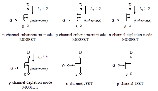
Figure 28 – Circuit symbols for FETs
A channel is created and the transistor is ON when the gate-to-source voltage breaks the threshold voltage (VT for MOSFETs and Vp for JFETs). For the three n-channel devices, the channel is created when
![]() (33)
(33)
Alternatively, for the p-channel devices, the channel is created when
![]() (34)
(34)
The threshold is positive for the enhancement NMOS, the depletion PMOS, and the p-channel JFET. It is negative for the depletion NMOS, the enhancement PMOS, and the n-channel JFET.
In order for the transistor to operate in the triode region, the drain-to-source voltage must obey the following inequalities:
For n-channel MOSFETs or JFETs,
![]() (35)
(35)
For p-channel MOSFETs or JFETs, the opposite is true. That is, to operate in the triode region,
![]() (36)
(36)
In either case, if the inequality is not obeyed, the transistor operates in the saturation region when it is on.
These relationships are summarized in Table 1.
Table 1 – FET Relationships
We now show the similarity in the equations for drain current for the MOSFET and JFET. In the saturation region, the drain current for the MOSFET is [Equation 8 ( Chapter: “2. Metal-oxide semiconductor FET (MOSFET)” )],
![]() (37)
(37)
where K is given by,
![]()
In the case of the JFET, the equivalent is [Equation 20 (Chapter: “3. Junction field-effect transistor (JFET)”)].
![]() (38)
(38)
This is identical to the equation for the MOSFET if we set VT equal to Vp, and equate the constants,
![]() (39)
(39)
The same equivalence is true for the triode region. We presented the drain current equation for the MOSFET [see Equation 4 (Chapter: “2. Metal-oxide semiconductor FET (MOSFET)”]
![]() (40)
(40)
This identical equation holds for the JFET with the substitution of Vp for VT, and the value of K given in Equation (39).
In summary, the only difference in the equations for the MOSFET and JFET are the values of the constant K, and the fact that the threshold voltage in the MOSFET is equivalent to the pinch-off voltage in the JFET.