
7. FET Models for Computer Simulations
 CURRENT – 7. FET Models for Computer Simulations
 PREVIOUS- 6. Comparison of MOSFET to JFET
FET Models for Computer Simulations
SPICE and MICRO-CAP contain sophisticated models for JFETs and MOSFETs. The JFET model (the SPICE 2G.6 model) contains 12 parameters. The MOSFET SPICE model contains 42 parameters in three levels. The lowest level model contains 25 parameters, while higher-order models add to this list. MICRO-CAP additional 10 parameters to the MOSFET model to bring the total to 52. The more parameters the model uses, the closer the simulation results are to the actual device operation. However, the more parameters in the model, the slower the simulation runs.
The reason there are so many parameters is that the model attempts to closely imitate the nonlinear operating curves of the device. The computer is capable of tracking far more details than we can by hand, so the model can be more sophisticated than that we use for a “paper” solution. In many analysis situations, you would set most of the model parameters to their default values and this complex model behaves almost the same as the simplified models we have discussed. While we discuss SPICE in an Appendix of this text, we will now quickly review the syntax for including a JFET or MOSFET in a circuit. The SPICE statement for a JFET is of the form,
Jname nd ng ns modelname [area] [OFF] [IC=vds[,vgs]]
Square brackets indicate that the quantity is optional. As an example, you might include statements,
![]()
The 10, 11 and 12 in the first statement are the node numbers for the drain, gate, and source. U308 is the model name. The area, which defaults to unity, multiplies or divides parameters for the model. The “OFF” instruction turns the JFET off for the first operating point. The “IC” sets initial conditions for the drain-to-source and gate-to-source voltages. The initial conditions are only used for transient analysis. The second statement is used to define the device having name U308 as an n-channel JFET with Vp (VTO) set to –4V and K(BETA) equal to K = IDSS/VP2. For a p-channel JFET use the designator PJF instead of NJF and set the parameters VTO and BETA to match the p-channel parameters.
The following table lists the 12 parameters in the computer simulation model. It also shows the default value and units for each parameter.
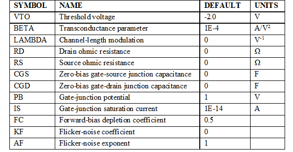
Table 2 – SPICE JFET Parameters
The model associated with these parameters is shown in Figure 29.
The SPICE MOSFET model is considerably more complex than that of the JFET. The lowest level (level 1) model contains 25 parameters which are detailed in Table 3. The SPICE statement is of the form:
Mname nd ng ns nb modelname
+[L=length][W=width][AD=drainarea][AS=sourcearea]
+[PD=drainperiphery][PD=sourceperiphery][NRD=drainsquares]
+[NRS=sourcesquares][NRG=gatesquares][NRB=bulksquares]
+[OFF][IC=vds][,vgs[,vbs]]]
![]() (29)
(29)
Square brackets indicate that the quantity is optional. As an example, you might include a statement,
![]()
This example specifies node numbers 1,2,3 and 0 for the drain, gate, source, and body of the device. Note that KP = 2K ( = 2IDSS/VP2). Use PMOS for p-channel instead of NMOS in the second statement.
![]()
The parameters, their default values and units, are given in Table 3. The model associated with these parameters is shown in Figure 30.
Figure 30 – MOSFET transistor model