
8. FET Amplifiers – Canonical configurations
 CURRENT – 8. FET Amplifiers – Canonical configurations
 PREVIOUS- 7. FET Models for Computer Simulations
FET Amplifiers – Canonical configurations
Figure 31 – FET amplifier – general configuration
Figure 31 shows a general configuration for an FET amplifier.
In this figure, we show the symbol for an n-channel JFET, but the configuration applies to other FET devices depending on the sign of the sources. The output (load) is connected to either point B or C, and the input is connected to either A or C.
Just as there were four basic configurations for the single-stage BJT amplifier, there are four configurations for the single-stage FET amplifier. These configurations are shown in Figure 32.
In Figure 32(a), we have provided an ac path from the JFET source terminal to the ground. The output is between drain and ground, and the input is between gate and ground. Since the JFET source terminal is common to both input and output, this is called a common-source (CS) amplifier. We will see in Section 9.1 that this configuration yields high input resistance and high voltage gain, but at the expense of high output resistance.
If the capacitance between the JFET source terminal and ground is removed in Figure 32(a), we have the common-source amplifier with source resistor (or source-resistor amplifier). This is analogous to the CE amplifier with emitter resistor (the emitter-resistor amplifier).
In Figure 32(b), we have (ac) grounded the gate terminal, taken the output from drain to ground, and applied the input signal between JFET source terminal to ground.
Since the gate is (ac) common to both input and output, this is known as the common-gate (CG) amplifier. We will see in Section 9.2 that this configuration provides high voltage gain and low output resistance, but at the expense of low input resistance. Because of the low input resistance, this configuration is often used as a current amplifier with a current gain close to unity (e.g., to isolate signals).
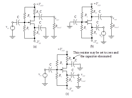
Figure 32 – FET single-stage amplifier configurations
Finally, Figure 32(c) shows a configuration with the drain grounded (ac), the signal input from gate to ground, and the output from the JFET source terminal to ground. Since the drain is common (ac) to both input and output, this is known as a common-drain (CD) configuration. Alternatively, it is called a source follower (SF) because of the way it operates. We shall see in Section “9.3 The CD (SF) Amplifier” that the voltage gain is close to unity with low output resistance and high input resistance. The output (JFET source terminal) therefore “follows” the input, and this configuration is often used as a buffer.