
3. The Non-Inverting Amplifier
 CURRENT – 3. The Non-Inverting Amplifier
 PREVIOUS- 2. The inverting amplifier
The Non-Inverting Amplifier
The op-amp can be configured to produce either an inverted or non-inverted output. In the previous section we analyzed the inverting amplifier. We now repeat the analysis for the non-inverting amplifier, as shown in Figure (5).
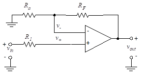
Figure 5- Non-inverting amplifier
We analyze this using the basic properties of the ideal op-amp. Since the current through R1 is zero,
(18)
Writing a node equation at the v– node yields,
(19)
We set v+ = v–, and substitute for v– to obtain,
(20)
The non-inverting gain is then given by,
(21)
We analyzed multiple-input inverting op-amps in previous Section (“The Inverting Amplifier”). We now analyze non-inverting op-amps with multiple inputs.
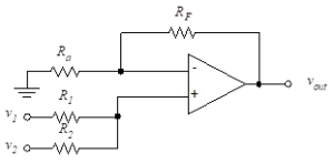
Figure 6- Two non-inverting inputs
Figure (6) illustrates a circuit with two input voltages. To find v+, we apply Kirchhoff’s current law to the non-inverting input terminal to yield (recall that the input current to the op-amp is zero),
(22)
Solving then for v+, we obtain
(23)
The inverting voltage, v–, is found from the node equation at v– with the result,
(24)
Setting v+ equal to v–, we obtain
(25)
APPLICATION
Analyze the following circuit using circuit simulation with TINACloud to determine Vout in terms of the input voltages by clicking the link below.
1-Two Non-inverting Inputs Circuit Simulation
In a practical sense, it is important to briefly consider the effects of loading on the op-amp. The method we have been using for analysis yields the correct voltage gain, based on the assumption that the current required from the dependent source of the ideal op-amp model is within the range set forth by the manufacturer’s data sheet for a real op-amp. Although we explore the practical considerations in later chapters, the next two examples illustrate the concept.
When analyzing both the inverting and the non-inverting configurations, we must be certain that the op-amp is capable of supplying sufficient current to drive the load resistor.
APPLICATIONS
Analyze the following circuits using the TINACloud online circuit simulator to determine Vout in terms of the input voltages by clicking the links below.