
2. The Inverting Amplifier
 CURRENT – 2. The inverting amplifier
 PREVIOUS- 1. Ideal op-amps
The Inverting Amplifier
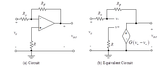
Figure 3- The inverting op-amp
Figure 3 (a) illustrates an inverting amplifier with the feedback, and Figure 3 (b) shows the equivalent circuit for this ideal inverting op-amp circuit. We have used the properties of the ideal op-amp to model the op-amp input as an open circuit. The controlled source is Gvd, but under the given assumptions, we will not have to use this information explicitly. We wish to solve for the output voltage, vout, in terms of the input voltage, va. We write equations for v+ and v– and then set these expressions equal to each other. Since the current through R is zero,
(12)
Also Kirchhoff’s node equation at v– yields,
(13)
Since v+ = v– and v+ = 0, then v– is also zero. Therefore, we have one equation in two unknowns, va and vout, so we can solve for the closed-loop gain as,
(14)
Notice that the closed-loop gain, vout /va, is negative (inverted) and is dependent only on the ratio of two resistors, RF /Ra. It is independent of the very high open-loop gain, G. This desirable result is caused by the use of feedback of a portion of the output voltage to subtract from the input voltage. The feedback from output to input through RF serves to drive the differential voltage, vd = v+ – v–, close to zero. Since the non-inverting input voltage, v+, is zero, the feedback has the effect of driving v– to zero. Hence, at the input of the op-amp,
(15)
No matter how complex the ideal op-amp circuit, by following this simple procedure the engineer can quickly analyze (and soon design) op-amp systems.
We may now expand this result to the case of multiple inputs.

Figure 4- Op-amp circuit
The amplifier shown in Figure (4) produces an output which is a negative weighted summation of several input voltages.
Since the current through R is zero, v+ = 0. The node equation at the inverting input terminal is given by Equation (16):
(16)
Since v+ = v–, then v+ = 0 = v– and we find vout in terms of the inputs as follows:
(17)
The extension to n inputs is straightforward.
APPLICATIONS
Analyze the following circuits using with the TINACloud circuit simulator to determine Vout in terms of the input voltages by clicking the links below.