
11. Coupling between Multiple Inputs
 CURRENT – 11. Coupling between Multiple Inputs
 PREVIOUS- 10. Amplifiers with balanced Inputs or Outputs
Coupling between Multiple Inputs
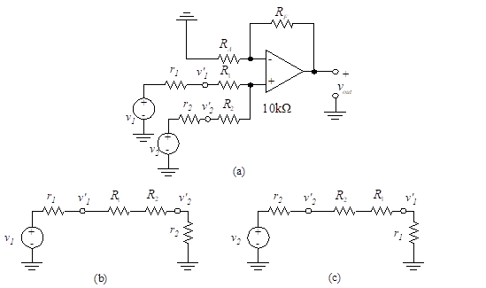
Figure 47 – Coupling between multiple inputs
The ideal source voltages, v1 and v2, have series resistances, r1 and r2 respectively. We begin by writing the equations for the effective voltages, v’1 and v’2, into the summing amplifier. We assume that zero current enters the op-amp. With v2 set equal to zero, as shown in Figure 47(b), the voltage into the op-amp, v’2, is
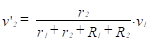
(98)
When v1 = 0, the v’1 voltage is [see Figure 47(c)],
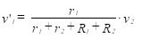
(99)
Notice that the v’2 voltage comes from v1 and the v’1 voltage comes from v2. This coupling effect produces undesirable cross-talk between the two inputs. The effect can be eliminated by designing a system with r1 and r2 approaching zero. Hence, to eliminate coupling, each non-inverting multiple input should be driven with an op-amp that has zero (or very low) output impedance.