 Click or Tap the Example circuits below to invoke TINACloud and select the Interactive DC mode to Analyze them Online.
 Get a low cost access to TINACloud to edit the examples or create your own circuits
1. DC BRIDGE NETWORKS
The DC bridge is an electrical circuit for the precise measurement of resistances. The best known bridge circuit is the Wheatstone bridge, named after Sir Charles Wheatstone (1802 – 1875), an English physicist and inventor.
The Wheatstone bridge circuit is shown in the figure below. The interesting feature of this circuit is that if the proyducts of the opposite resistances (R1R4 and R2R3) are equal, the current and voltage of the middle branch is zero, and we say that the bridge is balanced. If three of the four resistors (R1, R2, R3, R4) are known, we can determine the resistance of the fourth resistor. In practice the three calibrated resistors are adjusted until the voltmeter or ammeter in the middle branch reads zero.
Wheatstone bridges
Let’s prove the condition of balance.
When in balance, the voltages on R1 and R3 must be equal:
therefore
R1 R3+R1 R4 = R1 R3 + R2 R3
Since the term R1 R3 appears on both sides of the equation, it can be subtracted and we get the condition of balance:
R1 R4 = R2 R3
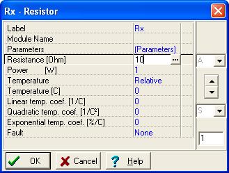
In TINA you can simulate balancing the bridge by assigning hotkeys to the components to be changed. To do this, double click on a component and assign a hotkey. Use a function key with the arrows or a capital letter, e.g. A to increase and another letter, e.g. S to decrease the value and an increment of say 1. Now when the program is in interactive mode, (the DC button is pressed) you can change the values of the components with their corresponding hotkeys. You can also double-click on any component and use the arrows on the right side of the dialog below to change the value.
Example
Find the value of Rx if the Wheatstone-bridge is balanced. R1 = 5 ohm, R2 = 8 ohm,
R3 = 10 ohm.
The rule for Rx
Checking with TINA:
If you have loaded this circuit file, press the DC button and hit the A key a few times to balance the bridge and see the corresponding values.
2. AC BRIDGE NETWORKS
The same technique can also be used for AC circuits, simply by using impedances instead of resistances:
In this case, when
Z1 Z4 = Z2 Z3
the bridge will be balanced.
If the bridge is balanced and for example Z1, Z2 , Z3 are known
Z4 = Z2 Z3 / Z1
Using an AC bridge, you can measure not only impedance, but also resistance, capacitance, inductance, and even frequency.
Since equations containing complex quantities mean two real equations (for the absolute values and phases or real and imaginary parts) balancing an AC circuit normally needs two operating buttons but also two quantities can be simultaneously found by balancing an AC bridge. Interestingly the balance condition of many AC bridges are independent of the frequency. In the following we will introduce the most well known bridges, each named after their inventor(s).
Schering – bridge: measuring capacitors with series loss.
The bridge will be balanced if:
Z1 Z4 = Z2 Z3
In our case:
after multiplication:
The equation will be satisfied if both real and imaginary parts are equal.
In our the bridge, only C and Rx are unknown. To find them we have to change different elements of the bridge. The best solution is to change R4 and C4 for fine-tuning, and R2 and C3 to set the measurement range.
Numerically in our case:
independent of the frequency.
At the calculated values the current equals zero.
Maxwell bridge: measuring capacitors with parallel loss
Find the value of the capacitor C1 and its parallel loss R1 if the frequency f = 159 Hz.
The condition of balance:
Z1Z4 = Z2Z3
For this case:
The real and imaginary parts after multiplication:
R1*R4 + j w L1*R1 = R2*R3 + j w R1 R2 R3C1
And from here the condition of balance:
Numerically R1 = 103*103/103 = 1 kohm, C1 = 10-3/106 = 1 nF
In the next figure you can see that with these value of C1 and R1 the current really is zero.
Hay bridge: measuring inductances with series loss
Measure the inductance L1 with series loss R4.
The bridge is balanced if
Z1Z4 = Z2Z3
After multiplying, the real and imaginary parts are:
Solve the second equation for R4, substitute it into the first criteria, solve for L1, and substitute it into the expression for R4:
These criteria are frequency dependent; they are valid only for one frequency!
Numerically:

om:=Vsw
L:=C1*R2*R3 / (1+om*om*C1*C1*R1*R1)
R:=om*om*R1*R2*R3*C1*C1 / (1+om*om*C1*C1*R1*R1)
L=[5.94070853]
R=[59.2914717]
#Lets simplify the print of complex
#numbers for greater transparency:
cp= lambda Z : “{:.8f}”.format(Z)
om=Vsw
L=C1*R2*R3/(1+om**2*C1**2*R1**2)
R=om**2*R1*R2*R3*C1**2/(1+om**2*C1**2*R1**2)
print(“L=”,cp(L))
print(“R=”,cp(R))
Checking the result with TINA:
Wien-Robinson bridge: measuring frequency
How can you measure frequency with a bridge?
Find the conditions for balance in the Wien-Robinson bridge.
The bridge is balanced if R4 ּ(R1 + 1/ j w C1 ) = R2 ּR3 / (1 + j w C3 R3)
After multiplication and from the requirement of equality of the real and imaginary parts:

If C1 = C3 = C and R1 = R3 = R the bridge will be balanced if R2 = 2R4 and the angular frequency:
 `
`
Checking the result with TINA:
{Double-click here to invoke the interpreter}
w:=1/(R1*C1)
f:=w/(2*pi)
f=[159.1549]
import math as m
w=1/(R1*C1)
f=w/(2*m.pi)
print(“f= %.4f”%f)