 Click or Tap the Example circuits below to invoke TINACloud and select the Interactive DC mode to Analyze them Online.
 Get a low cost access to TINACloud to edit the examples or create your own circuits
As we move from our study of DC circuits to AC circuits, we must consider two other types of passive component, ones that behave very differently from resistors–namely, inductors and capacitors. Resistors are characterized only by their resistance and by Ohm’s law. Inductors and capacitors change the phase of their current relative to their voltage and have impedances that depend upon frequency. This makes AC circuits much more interesting and powerful. In this chapter, you will see how the use of phasors will permit us to characterize all passive components (resistor, inductor, and capacitor) in AC circuits by their impedance and the generalized Ohm’s law.
Resistor
When a resistor is used in an AC circuit, the variations of the current through and the voltage across the resistor are in phase. In other words, their sinusoidal voltages and currents have the same phase. This in phase relationship can be analyzed using the generalized Ohm’s law for the phasors of the voltage and current:
VM = R*IM or V = R*I
Obviously, we can use Ohm’s law simply for the peak or rms values (the absolute values of the complex phasors)–
VM = R*IM or V = R*I
but this form does not contain the phase information , which plays such an important role in AC circuits.
Inductor
An inductor is a length of wire, sometimes just a short trace on a PCB, sometimes a longer wire wound in the shape of a coil with a core of iron or air.
The symbol of the inductor is L, while its value is called inductance. The unit of inductance is the henry (H), named after the famous American physicist Joseph Henry. As inductance increases, so too does the inductor’s opposition to the flow of AC currents.
It can be shown that the AC voltage across an inductor leads the current by a quarter of a period. Viewed as phasors, the voltage is 90° ahead (in a counterclockwise direction) of the current. In the complex plane, the voltage phasor is perpendicular to the current phasor, in the positive direction (with respect to the reference direction, counterclockwise). You can express this by complex numbers using an imaginary factor j as a multiplier.
The inductive reactance of an inductor reflects its opposition to the flow of AC current at a particular frequency, is represented by the symbol XL, and is measured in ohms. Inductive reactance is calculated by the relationship XL = w*L = 2*p*f*L. The voltage drop across an inductor is XL times the current. This relationship is valid for both the peak or rms values of the voltage and current. In the equation for inductive reactance (XL ), f is frequency in Hz, w the angular frequency in rad/s (radians/second), and L the inductance in H (Henry). So we have two forms of the generalized Ohm’s law:
1. For the peak (VM, IM ) or effective (V,I) values of the current and the voltage:
VM = XL*IM or V = XL*I
2. Using complex phasors:
VM = j * XL IM or V = j * XL * I
The ratio between the voltage and current phasors of the inductor is its complex inductive impedance:
ZL= V/I = VM / IM = j w L
The ratio between the phasors of the current and voltage of the inductor is its complex inductive admittance:
YL= I/V = IM /VM =1/ (j w L)
You can see that the three forms of the generalized Ohm’s law–ZL= V / I, I = V / ZL, and V = I * ZL–are very similar to Ohm’s law for DC, except that they use impedance and complex phasors. Using impedance, admittance, and the generalized Ohm’s law, we can treat AC circuits very similarly to DC circuits.
We can use Ohm’s law with the magnitude of inductive reactance just as we did for resistance. We simply relate the peak (VM, IM) and rms (V, I) values of the current and voltage by XL, the magnitude of inductive reactance:
VM = XL IM or V = XL * I
However, since these equations do not include the phase difference between the voltage and current, they shouldn’t be used unless phase is of no interest or is taken into account otherwise.
Proof The time function of the voltage across a pure linear inductor (an inductor with zero internal resistance and no stray capacitance) can be found by considering the time function that relates voltage and current of the inductor: Using the complex time function concept introduced in the previous chapter Using complex phasors: VL = j w L* IL or with real time functions vL (t) = w L iL (t+90°) so the voltage is 90° ahead of the current. |


Let us demonstrate the proof above with TINA and show the voltage and the current as time functions and as phasors, in a circuit containing a sinusoidal voltage generator and an inductor. First we will calculate the functions by hand.
The circuit we will study consists of a 1mH inductor connected to a voltage generator with sinusoidal voltage of 1Vpk and a frequency of 100Hz (vL=1sin (wt)=1sin(6.28*100t) V).
Using the generalized Ohm’s law, the complex phasor of the current is:
ILM= VLM/(jwL) =1/(j6.28*100*0.001)=-j1.59A
and consequently the time function of the current:
iL(t)=1.59sin (wt-90°) A.
Now let’s demonstrate the same functions with TINA. The results are shown in the next figures.
Note on the use of TINA: We derived the time function using Analysis/AC Analysis/Time Function, while the phasor diagram was derived using Analysis/AC Analysis/Phasor Diagram. We then used copy and paste to put the analysis results on the schematic diagram. To show the amplitude and phase of the instruments on the schematic, we used AC Interactive Mode.
The circuit diagram with the embedded time function and phasor diagram
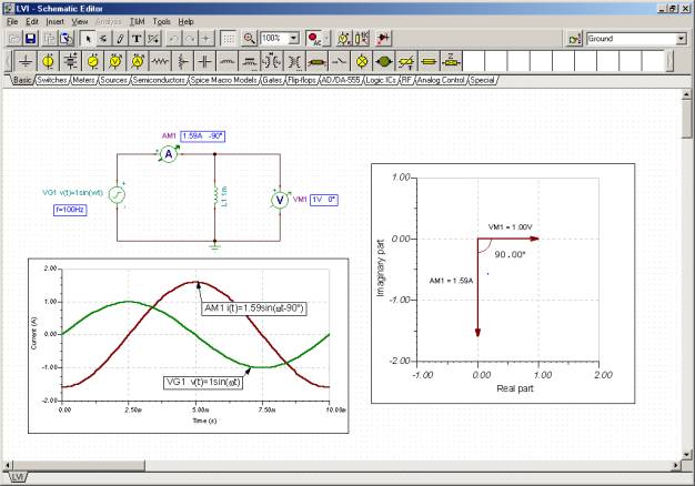
Time functions
Phasor diagram
Example 1
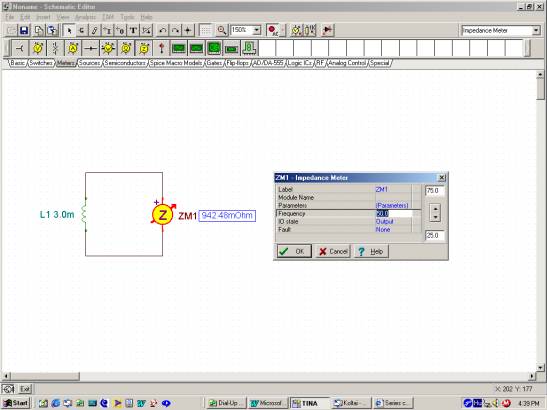
Find the inductive reactance and the complex impedance of an inductor with L = 3mH inductance, at a frequency f = 50 Hz.
XL = 2*p*f*L = 2*3.14*50*0.003 = 0.9425 ohm = 942.5 mohms
The complex impedance:
ZL= j w L = j 0.9425 = 0.9425 j ohms
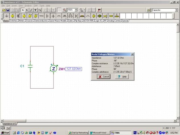
You can check these results using TINA’s impedance meter. Set the frequency to 50Hz in the property box of the impedance meter, which appears when you double click on the meter. The impedance meter will show the inductive reactance of the inductor if you press the AC Interactive mode button as shown in the figure, or if you select the Analysis/AC Analysis/Calculate nodal voltages command.
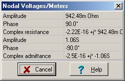
Using the Analysis/AC Analysis/Calculate nodal voltages command, you can also check the complex impedance measured by the meter. Moving the pen-like tester that appears after this command and clicking on the inductor, you will see the following table showing the complex impedance and admittance.
You can also show the complex impedance as a complex phasor using TINA’s AC Phasor Diagram. The result is shown in the next figure. Use the Auto Label command to put the label showing the inductive reactance on the figure. Note that you may need to change the automatic settings of the axes by double clicking to achieve the scales shown below.
Example 2
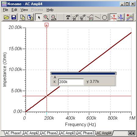
Find the inductive reactance of the 3mH inductor again, but this time at a frequency f = 200kHz.
XL = 2*p*f*L = 2*3.14*200*3 = 3769.91 ohms
As you can see, the inductive reactance rises with frequency.
Using TINA you can also plot the reactance as a function of the frequency.
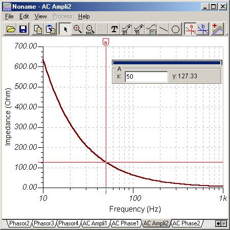
Select the Analysis /AC Analysis/AC transfer and set the Amplitude and Phase checkbox. The following diagram will appear:
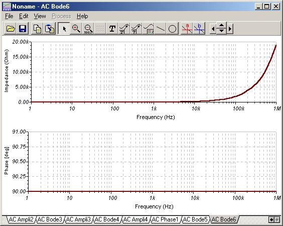
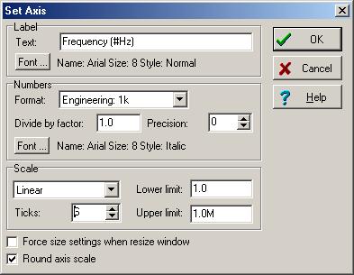
In this diagram the Impedance is shown on a linear scale against frequency on a logarithmic scale. This conceals the fact that the impedance is a linear function of frequency. To see this, double click on the upper frequency axis and set Scale to Linear and Number of Ticks to 6. See the dialog box below:
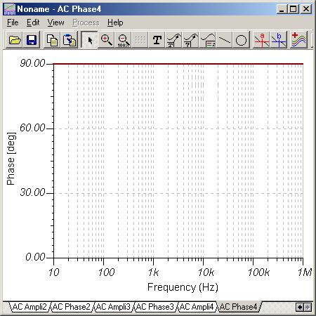
Note that in some older version of TINA the phase diagram may show very small oscillations around 90 degrees due to rounding errors. You can eliminate this from the diagram by setting the vertical axis limit similar to those shown in the figures above.
Capacitor
A capacitor consists of two conducting electrodes of metal separated by a dielectric (insulating) material. The capacitor stores electric charge.
The symbol of the capacitor is C, and its capacity (or capacitance) is measured in farads (F), after the famous English chemist and physicist Michael Faraday. As capacitance increases, the capacitor’s opposition to the flow of AC currents decreases. Furthermore, as frequency increases, the capacitor’s opposition to the flow of AC currents decreases.
The AC current through a capacitor leads the AC voltage across the
counterclockwise direction) the current. In the complex plane, the voltage phasor is perpendicular to the current phasor, in the negative direction (with respect to the reference direction, counterclockwise). You can express this by complex numbers using an imaginary factor –j as a multiplier.
The capacitive reactance of a capacitor reflects its opposition to the flow of AC current at a particular frequency, is represented by the symbol XC, and is measured in ohms. Capacitive reactance is calculated by the relationship XC = 1/ (2*p*f*C) = 1/wC. The voltage drop across a capacitor is XC times the current. This relationship is valid for both the peak or rms values of the voltage and current. Note: in the equation for capacitive reactance (XC ), f is frequency in Hz, w the angular frequency in rad/s (radians/second), C is the
in F (Farad), and XC is the capacitive reactance in ohms. So we have two forms of the generalized Ohm’s law:
1. For the absolute peak or effective values of the current and the voltage:
 or V = XC*I
2. For the complex peak or effective values of the current and the voltage:
VM = –j * XC*IM or V = – j*XC*I
The ratio between the voltage and current phasors of the capacitor is its complex capacitive impedance:
ZC = V/I = VM / IM = – j*XC = – j / wC
The ratio between the phasors of the current and voltage of the capacitor is its complex capacitive admittance:
YC= I/V = IM / VM = j wC)
Proof: The time function of the voltage across a pure linear capacitance (a capacitor with no parallel or series resistance and no stray inductance) can be expressed using the time functions of the capacitor’s voltage (vC), charge (qC) and current (iC ): If C does not depend on time, using complex time functions: or using complex phasors: or with real time functions vc (t) = ic (t-90°)/(w C) so the voltage is 90° behind the current. |

Let us demonstrate the proof above with TINA and show the voltage and the current as functions of time, and as phasors. Our circuit contains a sinusoidal voltage generator and a capacitor. First we will calculate the functions by hand.
The capacitor is 100nF and is connected across a voltage generator with sinusoidal voltage of 2V and a frequency of 1MHz : vL=2sin (wt)=2sin(6.28*106t) V
Using the generalized Ohm’s law, the complex phasor of the current is:
ICM= jwCVCM =j6.28*10610-7 *2)=j1.26A,
and consequently the time function of the current is:
iL(t)=1.26sin (wt+90°) A
so the current is ahead of the voltage by 90°.
Now let us demonstrate the same functions with TINA. The results are shown in the next figures.
The circuit diagram with the embedded time function and phasor diagram 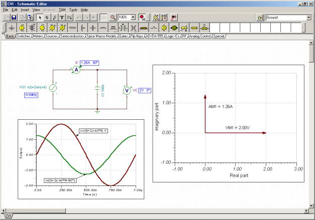
Time diagram
Phasor diagram
Example 3
Find the capacitive reactance and the complex impedance of a capacitor with C = 25 mF capacitance, at a frequency f = 50 Hz.
XC = 1/ (2*p*f*C) = 1/(2*3.14*50*25*10-6) = 127.32 ohms
The complex impedance:
Z-C= 1/ (j w C) = – j 127.32 = –127.32 j ohms
Let’s check these results with TINA as we did for the inductor earlier.
You can also show the complex impedance as a complex phasor using TINA’s AC Phasor Diagram. The result is shown in the next figure. Use the Auto Label command to put the label showing the inductive reactance on the figure. Note that you may need to change the automatic settings of the axes by double clicking to achieve the scales shown below.
Example 4
Find the capacitive reactance of a 25 mF capacitor again, but this time at frequency f = 200 kHz.
XC = 1/ (2*p*f*C) = 1/(2*3.14*200*103*25*10-6) = 0.0318 = 31.8 mohms.
You can see that the capacitive reactance decreases with frequency.
To see the frequency dependence of the impedance of a capacitor, let’s use TINA as we did earlier with the inductor.
The generalized Ohm’s law:
Z = V / I = VM/IM
The complex impedance for the basic RLC components:
ZR = R; ZL = j w L and ZC = 1 / (j w C) = –j / wC
We have seen how the generalized form of Ohm’s law applies to all components–resistors, capacitors, and inductors. Since we have already learned how to work with Kirchoff’s laws and Ohm’s law for DC circuits, we can build upon them and use very similar rules and circuit theorems for AC circuits. This will be described and demonstrated in the next chapters.